

")
")


Request for Quotation
Thank you for using our services
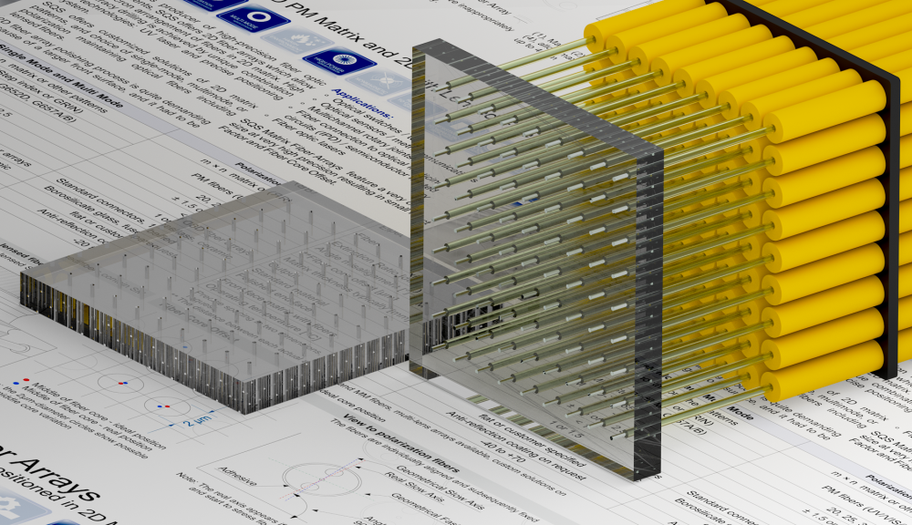
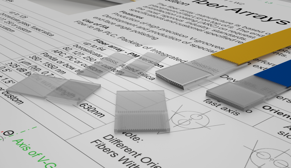
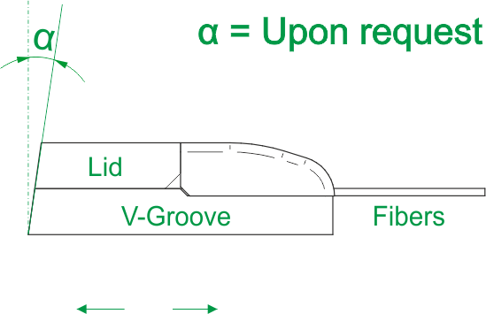
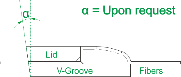
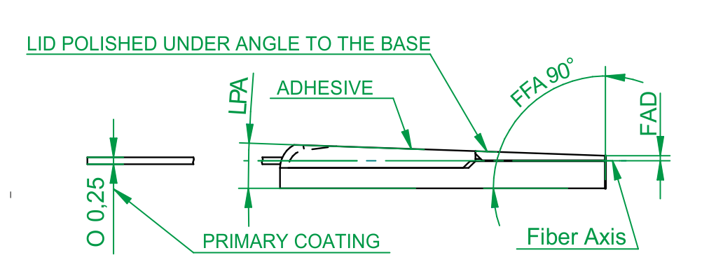
The fiber array manufacture is based on placing fiber in the high precision V-Groove Chip with another flat V-Groove Lid on top of it. The end face of the fiber array is optically polished, and on request available also with antireflection coating (ARC).
SQS Fiber Optic Arrays are manufactured and tested to the most rigorous industry standards. Their optical and mechanical performance meets IEC specifications and customer specified requirements.
Features:
- Manufacturing according to customer requirements (standard drawing or custom solution)
- High precision of fiber core positioning (core offset < 0,5 µm)
- PM fiber available (polarization extinction ratio PER > 25 dB)
- Single mode, multimode fiber
- Custom solutions available
- Atypical end face angle polishing available on request
Design:
- From Single Channel up to 128 Channels
- Many types of material (borosilicate glass, fused silica)
Applications:
- Fibers to PLCs
- Fibers to lens arrays
- Detectors
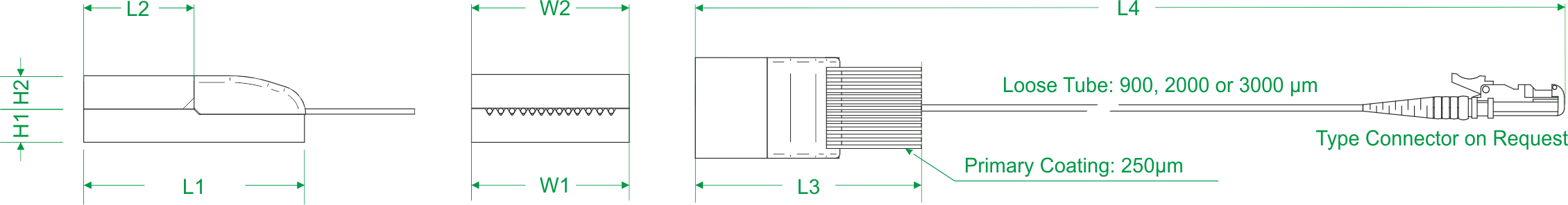
Specification Fiber Array
| SM Version | MM/PM/MCF/SM-SPEC /* Version | |
| Channels | specified by customer | specified by customer |
| V-groove/lid material | borosilicate glass, fused silica | borosilicate glass, fused silica |
| V-groove pitch | 82, 127, 250 or custom | 82, 127, 250 or custom |
| Polished end face | APC, PC or custom | APC, PC or custom |
| Fiber type | SM | Panda or Bow - tie or MCF |
| Operating wavelenght | 1260 - 1650 nm | 400 - 1950 nm |
| Fiber core offset ** | <0.7 um (typ. 0.5 µm) | <1 µm (typ. 0.7 µm) |
| Extinction ratio | - | ≥25 dB for the wavelength > 630nm |
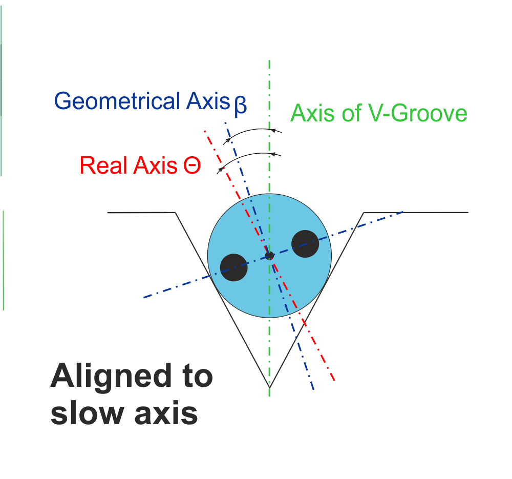
| Angle Misalignment β (GEO axis) | - | ± 0.5° |
| Angle misalignment Θ [°] | - | ± 2.5° |
| Operating temperature | -40 +85°C or custom | -20 +80°C or custom |
| Anti-reflection coating on end face | available on request | available on request |
* Fiber type and manufacturer must be approved in advance **Limited by number of channels
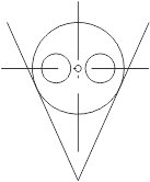
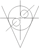
| Orientation of PM Fiber and MC Fiber | |||
| Aligned to Fast Axis | Aligned to Slow Axis | Custom Alignment | MC Fiber Alignment |
 |
 |
 |
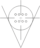 |
| Note: Different orientation of polarization maitaning or MCF fibers within fiber array is possible. | |||
| FRONT FACE POLISHING ANGLE ...FFA | LID OPTIMALIZATION FOR PIC COUPLING | ||
| Shorter Lid | Longer Lid | Shorter right | |
 |
 |
 |
|
 |
|||
 |
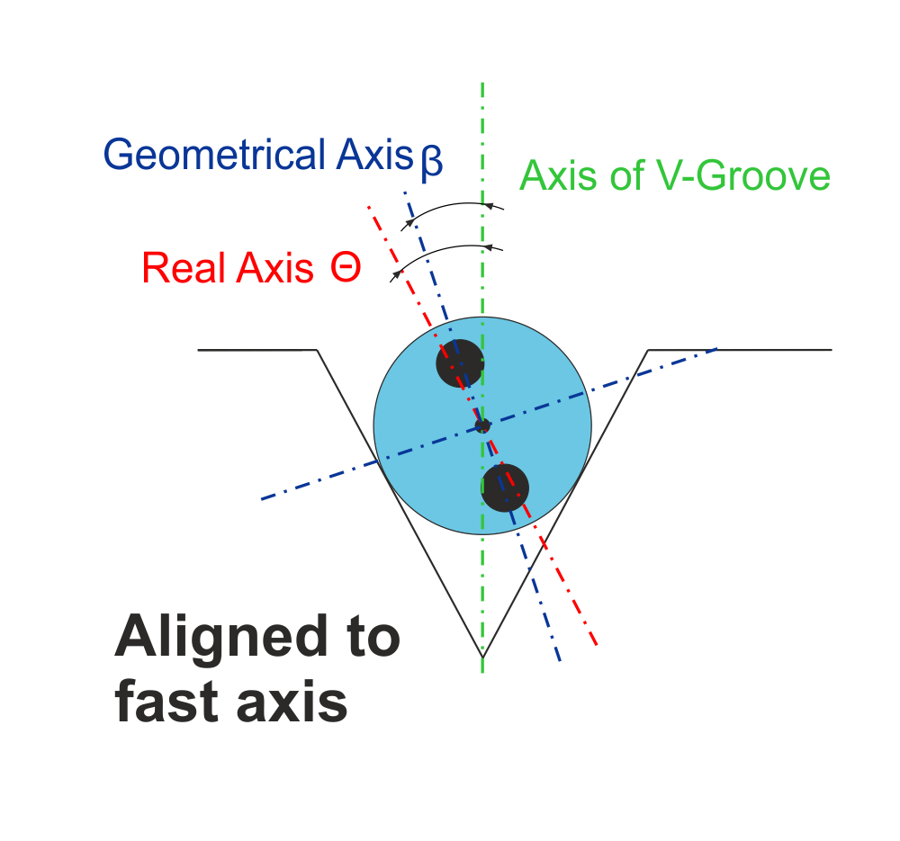 |
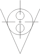
Angle Misalignment (Θ)
The angle misalignment Θ informs us of how precisely the PM fiber array was assembled. It shows the maximum angle between the real axis of the PM fiber and the v-groove axis of the fiber array. Angle misalignment affects total PER of two mated PM fiber arrays.
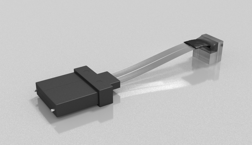
Examples of use