

")
")


Request for Quotation
Thank you for using our services
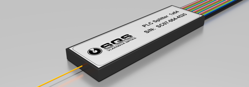
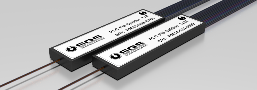
PM planar splitter maintains polarization of input optical signal. PM splitters are supplied in configurations with 2, 4, and 8 output channels.
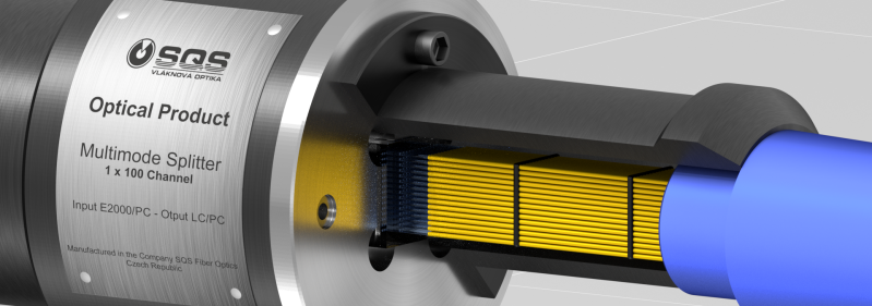
Polarization maintaining optical splitter is an optical splitter in which the polarization of linearly polarized light waves launched into the fiber is maintained during propagation, with little or no cross−coupling of optical power between the polarization modes. Such splitters are used in special applications where preserving polarization is essential e.g. laboratory, sensor technology and other industrial or medical applications. We can produce PM Splitters for launching the polarized lihgt into one axis (slow or fast) or into two axes (e.g. 45°). Polarization extinction ratio (PER) of SQS PM Splitters typically exceeds 25 dB.
Generally, SQS PLC splitters (incl. PM versions) are characterized as uniform broadband power splitters featuring exceptional uniformity of insertion loss throughout all channels resulting in fact in practical wavelength independency over all transmission range from 1260 to 1650 nm. Total value of insertion loss itself typically exceeds theoretical values just by minimum.
Real broadband performance:
- Low insertion loss and its uniformity within the whole wavelength range between 1260 and 1650 nm.
- High value of extinction (PER) > 25 dB
Applications:
- Excellent for laboratory and industrial applications
- Sensor technology
- Fiber optic measurement equipment and systems
Symetrical PM Splitters
| PLC splitters PM 1xN | IL max: [dB] | Pola- rization extincion ratio: [dB] | Uniform. max: [dB] | RL: [dB] | Dire- ctivity: [dB] | Wave- length range: [nm] | Fiber Type | Operating and Storage Temp. [°C] | Pigtail style 250 µm [mm] | Pigtail style 900 µm [mm] | Pigtail style 2 mm [mm] |
| PLC 1x2 | 4 | ≥25 | 0.5 | ≥55 | ≥55 | 1260 - 1650 | PM13, PM 15 or demand | -20 to +60 | 5.6 x 10 x 69 | 5.6 x 10 x 69 | 7.5 x 12 x 90 |
| PLC 1x3 | 6.5 | ≥25 | 0.8 | ≥55 | ≥55 | 1260 - 1650 | PM13, PM 15 or demand | -20 to +60 | 5.6 x 10 x 69 | 5.6x10 x 69 | 7.5 x 12 x 90 |
| PLC 1x4 | 8.1 | ≥25 | 0.8 | ≥55 | ≥55 | 1260 - 1650 | PM13, PM 15 or demand | -20 to +60 | 5.6 x 10 x 69 | 5.6 x 10 x 69 | 7.5 x 12 x 90 |
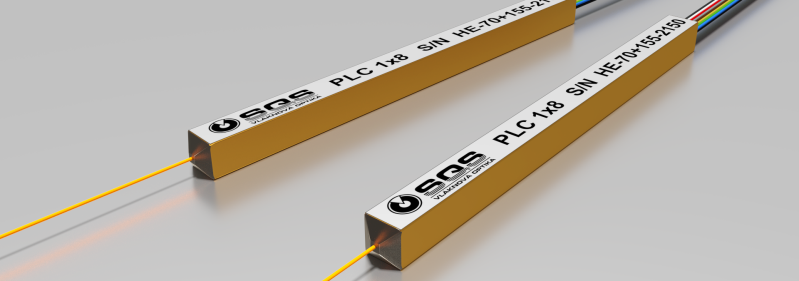
| PLC 1x8 | 11.2 | ≥25 | 1.0 | ≥55 | ≥55 | 1260 - 1650 | PM 13, PM 15 or demand | -20 to +60 | 5.6 x 10 x 69 | 5.6 x 10 x 69 | 7.5 x 12 x 90 |
| PLC 1x24 | 18 | ≥20 | 2.0 | ≥55 | ≥55 | 1260 - 1650 | PM 13, PM 15 or deman | -20 to +60 | 5.6x10x69 | on request | on request |
Specification of Asymmetrical PM Splitters, Spliting ratio 60/40%, 70/30%, 80/20%, 90/10%, 95/5%, 98/2%
| PLC Asymm. splitters | Ratio [%] | Pola- rization extincion ratio: [dB] | IL max:[dB] | Pola- rization dependent loss [dB]. max: [dB] | RL: [dB] | Dire- ctivity: [dB] | Wave- length range: [nm] | Fiber Type | Operating and Storage Temp. [°C] | Pigtail style 250 µm and 900 µm [mm] | Pigtail style 2 mm [mm] | |
| PLC 1x2 | 6/40 | ≥25 | 3.9/4-6 | ≤0.2 | ≥55 | ≥55 | 1260 - 1650 | PM13, PM 15 or demand | -20 to +60 | 5.6 x 10 x 69 | 7.5 x 12 x 90 | |
| PLC 1x2 | 70/30 | ≥25 | 3.5/5-7 | ≤0.2 | ≥55 | ≥55 | 1260 - 1650 | PM13, PM 15 or demand | -20 to +60 | 5.6 x 10 x 69 | 7.5 x 12 x 90 | |
| PLC 1x2 | 80/20 | ≥25 | 3.0/7-9 | ≤0.2 | ≥55 | ≥55 | 1260 - 1650 | PM13, PM 15 or demand | -20 to +60 | 5.6 x 10 x 69 | 7.5 x 12 x 90 | |
| PLC 1x2 | 85/15 | ≥25 | 2.5/8-10 | ≤0.2 | ≥55 | ≥55 | 1260 - 1650 | PM 13, PM 15 or demand | -20 to +60 | 5.6 x 10 x 69 | 7.5 x 12 x 90 | |
| PLC 1x2 | 90/10 | ≥25 | 2.0/9-12 | ≤0.2 | ≥55 | ≥55 | 1260 - 1650 | PM 13, PM 15 or deman | -20 to +60 | 5.6 x 10 x 69 | 7.5 x 12 x 90 | |
| PLC 1x2 | 95/5 | ≥25 | 1.5/12-15 | ≤0.2 | ≥55 | ≥55 | 1260 - 1650 | PM 13, PM 15 or deman | -20 to +60 | 5.6 x 10 x 69 | 7.5 x 12 x 90 | |
| PLC 1x2 | 98/2 | ≥25 | 1.2/15-18 | ≤0.2 | ≥55 | ≥55 | 1260 - 1650 | PM 13, PM 15 or deman | -20 to +60 | 5.6 x 10 x 69 | 7.5 x 12 x 90 | |
*) Depends on fiber type. Shorter wavelengths available.
**) w/o connectors
Diagram PLC Splitter 1x8
| Optical Parameters PLC Splitter 1x8 | Temperature Test PLC Splitter 1x8 |
 |
 |